Detail notes on

ISOMETRIC DRAWING

Isometric drawing is a method of representing three-dimensional objects on a two-dimensional surface. It provides a realistic and accurate representation of an object by showing all three axes (length, width, and height) in equal proportions. In isometric drawings, the object is viewed from an angle that preserves the relative proportions of the object's sides, resulting in a three-dimensional appearance.

Types of Isometric Drawing

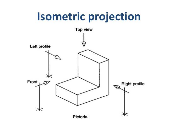
Isometric Projection

In isometric projection, the object is viewed from an angle of 30 degrees from the horizontal plane. This angle provides a balanced representation of the object and is commonly used in engineering and technical drawings.

Read More

Dimetric Projection

In dimetric projection, the object is viewed from an angle where two of the three axes are equally foreshortened, while the third axis remains at its true length. Dimetric projection is less commonly used but can be used to represent objects with uneven dimensions.

Read More

Trimetric Projection

In trimetric projection, all three axes are unequally foreshortened. Trimetric projection is rarely used for technical drawings due to the complexity of representing objects accurately.

Read More

Drawing an Isometric Drawing Physically

To draw an isometric drawing manually, you will need:

  1. Isometric graph paper: This special graph paper has evenly spaced equilateral triangles that aid in drawing the isometric projection accurately.

  2. Drawing tools: Pencil, ruler, and compass for precise measurements and lines.

Here are the steps to draw an isometric drawing manually:

  1. Determine the scale: Decide on the scale for your drawing. For example, you may choose that each unit on the isometric graph paper represents 1 inch or 1 centimeter.

  2. Select the object: Decide on the object you want to draw in isometric projection. Visualize its shape and dimensions.

  3. Draw the base: Start by drawing the base of the object on the isometric graph paper using light, construction lines. Ensure that the lines are parallel to the edges of the graph paper.

  4. Add height: Use the scale and measurements to determine the height of the object. Draw the vertical lines upward from the corners of the base, connecting them to form the sides of the object.

  5. Add depth: Similar to step 4, use the scale and measurements to determine the depth of the object. Draw lines from the corners of the base, connecting them to the corresponding corners on the height lines.

  6. Erase construction lines: Once you have drawn the object’s final shape, erase any construction lines that are no longer needed.

Drawing an Isometric Drawing in AutoCAD

AutoCAD is a computer-aided design (CAD) software widely used for creating technical drawings, including isometric projections. Here’s how you can draw an isometric drawing in AutoCAD:

  1. Open AutoCAD: Launch the AutoCAD software on your computer.

  2. Set the drawing units: Set the drawing units according to your preference. For example, you can set it to inches or millimeters.

  3. Set the isometric plane: Type “SNAP” in the command line and press Enter. In the Snap and Grid tab of the Drafting Settings dialog box, select “Isometric snap” and click OK.

  4. Draw the base shape: Use the line or polyline tool to draw the base shape of the object on the isometric plane. Ensure that you draw the lines at the correct angles to create an isometric projection.

  5. Extrude the shape: Select the base shape, and then use the “Extrude” command to give it height. Specify the desired height or extrusion distance.

  6. Modify the view: You can rotate the view to see the isometric projection from different angles using the “3DORBIT” command or by using the “ViewCube” tool.

  7. Add details: Use other drawing tools, such as lines, circles, arcs, or rectangles, to add details and features to your object.

  8. Save your drawing: Once you have completed the isometric drawing, save your file in the desired format.

Remember that learning and practicing AutoCAD commands and tools are essential to efficiently create isometric drawings in the software.

Contact

Contact Information

Below you can see the necessary information if you like to contact to use.