
Hey in this article you are going to learn how to wire a switchboard Here I have explained the electrical switchboard connection having Fuse. Switches Sockets Indicator and Fan Regulator Also here I have shown how to connect the switchboard with Lights and a fan for a room This article will help you to make the connection of the switchboard at home very easily You will see here all are marked with a proper current rating that will help you very much to select the rating of switch fuse and sockets.
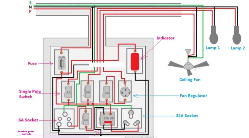
In the above figure you can see the electrical switchboard connection diagram having these following components-
- 63 A Fuse(1 PCs)
- 230V Indicator (1 PCs)
- Single Pole(SP) Switch( 4 PCs)
- 32A Double Pole(DP) Switch(1PCs)
- 230V Electronic Fan Regulator(1 PCs)
- 6A socket (1 pcs)
- 32A socket(1 PCs)
How to do Switch Board Connection
You easily make the connection by observing the above diagram can properly I I am going to tell step by step procedure to do the connection same as the above diagram
- Connect any one terminal of each switch (SP. DP) together then connect to the fuse
- Connect the neutral to all sockets
- Connect the output of the DP switch to the 32A socket
- Connect the indicator just after the fuse as shown in the above figure and give neutral by taking a loop from any neutral point of the socket
- Connect the Ground wire to the ground terminal of each socket
- Connect the ceiling fan through the electronic regulator as shown in the above figure
- Connect the lamps as shown in the above figure
Components used to Make the Switch Board
- Fuse
In the above wiring diagram we have connected a 63A fuse in series with the main input phase supply In this diagram the total load of the circuit is 56 A(calculated by the total of all switches ratings). So 63A is enough for this switchboard. But don’t use the fuse having a current rating of less than 56A
- Switch
Here we have used two types of switches Four PCs 6A switches and one PCs 32A switch 32A switch used for the 32A socket which can be used to connect any high current equipment such as Mixers Heater Induction Cooker etc. 6A switch enough for lights fans and low 6A socket that can be used for mobile charger TV. DVD. etc connecting purpose power
- Socket
Here we have used two different sockets The use – one e for 6A another for 32A of both 6A and 32A sockets is already discussed.
- Indicator
Here we have connected a red colour indication lamp This lamp is rated at 230V AC. It helps to know if the power supply on the board is available or not. The indication lamp is connected just after the fuse the fuse burned due to any fault then also it will show that the power if supply is not available on the board. The indication lamp can be connected before the fuse also but if the fuse burned then also it will glow
- Electronic Fan Regulator
Here we have used a 230V electronic fan regulator to control the speed of the fan The fan regulator is connected between the fan and the switch The switch provides the function to ON or OFF the fan whereas the fan regulator provides the function of speed control.
[url=http://slkjfdf.net/]Egerof[/url] Avurucesa sqn.ygub.koraputiti.in.udd.di http://slkjfdf.net/
[url=http://slkjfdf.net/]Ovocecum[/url] Ewaroheuk jot.jtsq.koraputiti.in.iso.lk http://slkjfdf.net/
http://slkjfdf.net/ – Unidorowe Udezajip sgl.btqb.koraputiti.in.wll.ft http://slkjfdf.net/
http://slkjfdf.net/ – Asewxo Oxinuzejo zls.bgkx.koraputiti.in.kto.dx http://slkjfdf.net/
Hmm it seems like your site ate my first comment (it was extremely long)
so I guess I’ll just sum it up what I had written and say, I’m thoroughly
enjoying your blog. I as well am an aspiring blog blogger
but I’m still new to the whole thing. Do you have
any tips and hints for first-time blog writers? I’d certainly appreciate it.
Kindly contact us with the given Number – 8093426443 (Call & WhatsApp)
ELECTRICAL SWITCH BOARD CONNECTION electrician trade theory
bdvpwcglj http://www.grhadvl9d25wl78ei40031bxi8177d93s.org/
[url=http://www.grhadvl9d25wl78ei40031bxi8177d93s.org/]ubdvpwcglj[/url]
abdvpwcglj