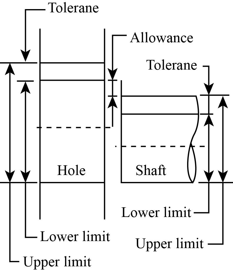
The maximum or minimum allowable sizes within which the size of component lies are known as limits. The limits are classified into two types:
- Upper limit
- Lower limit
Upper limit
The maximum permissible size or largest acceptable size of the component is called the upper limit of size.
Lower limit
The minimum permissible size or smallest acceptable size of the component is called the lower limit of size.
The diagrammatical representation of limits of size is shown as:

Fits
A fit is described as a relative motion between the components, generally hole and shaft resulting from their size achieved during their manufacturing.
It is also defined as the degree of looseness or tightness among two mating parts.
Following are the classification of fits based on the combination between shaft and hole:
- Clearance fit
- Transition fit
- Interference fit
Clearance fit
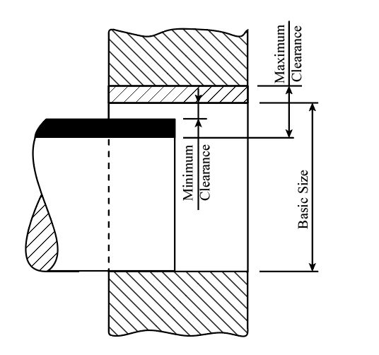
The clearance fit results when the shaft size is always less than the hole size for all possible combinations lying in the tolerance range.
In a clearance fit, the relative motion between the shaft and hole is always possible. In this, the lower limit size of the hole is greater or equal to the upper limit size of the shaft.
The minimum clearance is obtained at the maximum shaft size and the minimum hole size in the clearance fit. In contrast, the maximum clearance is obtained at the minimum shaft size and the maximum hole size.
The diagrammatical representation of the clearance fit is shown as:

Transition fit
The transition fit results when the shaft and hole are precisely the exact sizes.
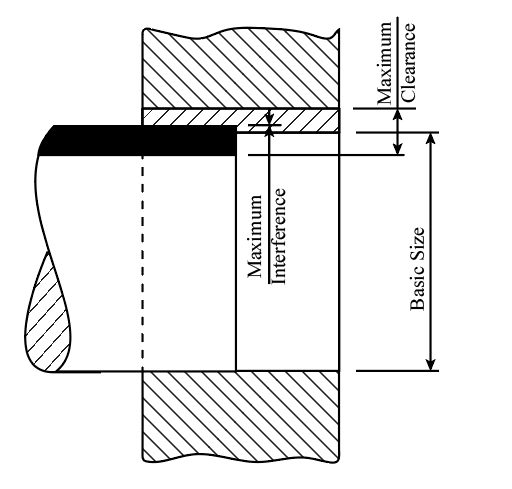
It is a boundary between clearance and interference and is achieved practically with selective assembly or careful machining methods within very few limits.
The practical transition fits occur when the tolerance is so that the largest hole is greater than the smallest shaft and the largest shaft is greater than the smallest hole.
In transition fit, the relative motion between shaft and hole is possible when clearance exists but not possible when interference exists.
The diagrammatical representation of the transition fit is shown as:

Interference fit
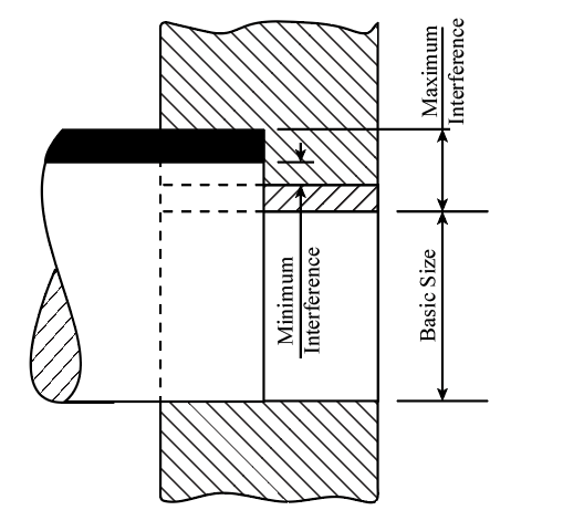
The interference fit results in the minimum shaft size being larger than the maximum hole size for all possible combinations in the given range. In interference fit, the relative motion between the shaft and hole is impossible.
The maximum interference occurs at the minimum shaft size and maximum hole size in an interference fit. In contrast, the maximum interference occurs at the maximum shaft size and minimum hole size.
The diagrammatical representation of the interference fit is shown as:

